Project Overview: This project explores the feasibility of controlling an elevator system wirelessly to reduce infrastructure costs and mechanical complexity. By implementing Frequency Shift Keying (FSK) modulation and demodulation circuits, we successfully transmitted digital control signals through an air medium to drive a stepper-motor-based elevator mechanism.
Introduction
Modern elevators are marvels of engineering, but they are tethered—literally—by complex wiring and communication infrastructure. The “traveling cable” in an elevator shaft is heavy, expensive, and prone to wear.
We asked a simple question: Can we cut the cord?
Our team designed a wireless control system that replaces physical signal wires with radio frequency communication. Using Frequency Shift Keying (FSK), we modulate digital data (button presses) into analog sine waves, transmit them wirelessly, and demodulate them on the receiver end to control the elevator’s logic and movement.
System Architecture
1. The Communications Protocol: FSK
We chose Frequency Shift Keying (FSK) for its noise immunity advantages over Amplitude Shift Keying (ASK). In our design:
- Logic High (1): Represented by a high-frequency carrier (14 kHz).
- Logic Low (0): Represented by a low-frequency carrier (7 kHz).
2. The Transmitter (Modulator)
The transmitter consists of two main stages: Signal Generation and Mixing.
Wien Bridge Oscillators To generate the carrier frequencies, we built two Wien Bridge Oscillators. These rely on an RC network to determine the resonant frequency. One oscillator was tuned to 7 kHz and the other to 14 kHz.
The resonant frequency \(f_r\)is determined by the resistance\(R\)and capacitance\(C\) values:
\[f_r = \frac{1}{2\pi RC}\]The Mixer (Class B Amplifier) We used a switching circuit acting as a Class B amplifier to mix the two carriers.
- When the digital data signal is High, the NPN transistor activates, passing the 14 kHz wave.
- When the signal is Low, the PNP transistor activates, passing the 7 kHz wave.
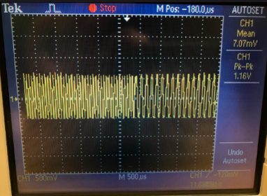 Figure 1: The FSK modulated output. Note the distinct shift in frequency density representing binary data.
3. The Receiver (Demodulator)
Once the signal is received, it must be converted back into a clean digital square wave for the microcontroller.
- Low Pass Filter: Smooths the received FSK wave into an amplitude-varying signal.
- Envelope Detector: Detects the edges of the signal.
- Decision Circuit (Comparator): Compares the input voltage against a reference voltage (2.5V). If the input is higher, it outputs a digital HIGH; otherwise, it outputs LOW.
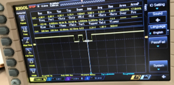 Figure 2: The clean digital square wave recreated by the comparator circuit.
Electromechanical Design
Motor Selection
We tested three motor types to drive the elevator shaft:
- Servo Motors: Rejected due to “jitter” caused by back-feeding noise into the FSK circuit, which triggered phantom floor calls.
- DC Motors: Rejected due to insufficient torque for lifting the carriage against gravity.
- Stepper Motors (Nema 17): Selected. They provided the necessary holding torque and precise position control required for aligning the elevator with floor levels.
The stepper motor is driven by an L298N driver and controlled by an Arduino Mega, which handles the floor logic (e.g., priority queues for Up/Down requests).
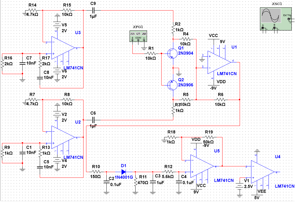 Figure 3: The complete system schematic showing the transmitter, receiver, and motor driver interfaces.
Implementation & Results
Waveform Analysis
Using an oscilloscope, we verified the integrity of the signal at each stage. The Wien Bridge oscillators produced clean sine waves, and the mixer successfully shifted frequencies based on the input bitstream.
However, we observed that the “receiver” waveform often looked like a noisy radio wave. The low-pass filter was critical in cleaning this artifact before the decision circuit processed it.
Video Demo
Below is a video demonstration of the wireless elevator responding to floor calls.
Challenges & Novel Insights
Key Findings:
-
The Range Limitation: Using basic 433MHz modules, we encountered severe signal degradation over short distances. If the transmitter and receiver moved just a few inches apart, the signal dropped, causing the elevator to become unresponsive.
-
Antenna Tuning: To mitigate the range issue, we calculated the optimal antenna length. For a 433MHz signal, a quarter-wave antenna is approximately 17 cm (\(\lambda / 4\)). \(\lambda = \frac{c}{f} = \frac{3 \times 10^8}{433 \times 10^6} \approx 0.69m \implies \frac{0.69}{4} \approx 0.17m\) Adding a 17cm wire antenna significantly improved connection stability, though random interference remained a challenge.
-
Power Supply Isolation: The stepper motors draw high current, which creates voltage dips. Initially, sharing a power rail between the motors and the sensitive FSK receiver caused the microcontroller to reset or behave erratically. Isolating the motor power supply was mandatory for reliable operation.
Conclusion
This project demonstrated that FSK is a viable method for wireless elevator control, offering a way to reduce cabling costs. While we successfully built the modulation hardware and logic software, the reliability of the system heavily depends on RF signal quality.
For a commercial application, error correction algorithms (like checksums) and more powerful transceivers (like LoRa or Zigbee) would be necessary to ensure passenger safety and system robustness.