Project Overview: The Devastating Driving Prevention Device (DDPD) is a custom-built hardware simulator designed to help novice drivers build confidence in a safe environment. By integrating Force Sensing Resistors (FSR), an ADXL335 Accelerometer, and NI LabVIEW, we created a functional steering and pedal system compatible with racing simulators like Mario Kart and Asphalt 9.
Introduction
Traffic accidents have seen a statistically significant rise, particularly following the pandemic. In 2020 alone, vehicle-related fatalities peaked at 11.67 deaths per 100,000 people. A major contributing factor is inexperienced or “unconfident” drivers who lack a safe environment to practice defensive driving skills without the life-or-death stakes of real traffic.
To address this, we developed the DDPD. Inspired by high-end racing gear like the Logitech G923, our goal was to engineer a low-cost alternative that replicates the physics of driving—steering, braking, and acceleration—using off-the-shelf sensors and signal processing.
System Architecture
The system consists of two main components: the physical hardware interface and the software processing unit (LabVIEW).
1. Hardware Design
The physical build utilizes a “cardboard and wood” chassis approach to keep costs low while maintaining functionality:
- Steering: An ADXL335 Accelerometer mounted to a Wii Wheel acts as the steering column. It measures the X-axis tilt to determine left/right direction.
- Pedals: Two Force Sensing Resistors (FSR) are mounted on wooden blocks to simulate gas and brake pedals.
- Immersion: A 12V DC Fan, controlled via a transistor circuit, provides wind feedback based on the simulated vehicle’s speed.
- Controller: An Arduino Uno handles data acquisition, reading analog voltages from the sensors and sending them to the PC.
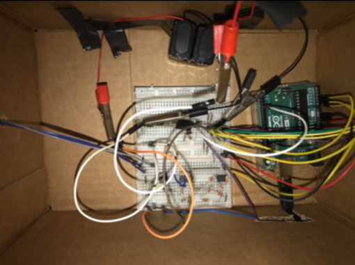 Figure 1: The DDPD Hardware Setup. Top: The signal conditioning circuit. Bottom: The physical chair, wheel, and pedal configuration.
2. Signal Conditioning Circuits
Raw sensor data is rarely usable immediately. We implemented three signal conditioning circuits:
- Op-Amp Amplifiers: To condition the accelerometer signals for the Arduino’s 0-5V analog input range.
- Voltage Dividers: To convert the varying resistance of the FSRs into readable voltage changes.
- Transistor Amplifier: To drive the high-power fan using low-power logic signals from the Arduino.
The Mathematics of Sensing
To turn physical force into digital control, we had to derive specific transfer functions for our sensors.
Force Sensing Resistors (Pedals)
The FSRs decrease in resistance as force is applied. We treated the system using a linear approximation where we mapped Force (\(F\)) to Resistance (\(R\)). Using the equation \(F = ma\), we determined the operating range was between 0.196N and 19.6N.
We utilized the linear equation \(R = m \cdot F + b\), solving for the slope \(m\):
\[m = \frac{\Delta R}{\Delta F}\]By plugging this back into the voltage divider equation, we could map the input voltage read by the Arduino directly to the “pressure” applied by the user’s foot.
Accelerometer (Steering)
The ADXL335 outputs voltage based on orientation relative to gravity. To get precise steering, we had to map the binary digital values to voltage, and then to a normalized position vector (\(-1\)to\(1\)).
We found the minimum input voltage to be approx. 1.28V and the maximum to be 1.95V. We applied a linear transformation:
\[V_{out} = m \cdot V_{in} + b\]Solving for the slope \(m\) to map this to our 0-5V logic:
\[m = \frac{5}{1.95313 - 1.27930} \approx 7.42\] \[b = 7.4203(V_{in_{min}}) = 9.49\]This allowed us to define a “Dead Zone” in the center for straight driving, while converting positive voltage deltas to “Right” turns and negative deltas to “Left” turns.
Software Implementation (LabVIEW)
The software core was built entirely in NI LabVIEW. It handles Data Acquisition (DAQ), Signal Processing, and Game Control.
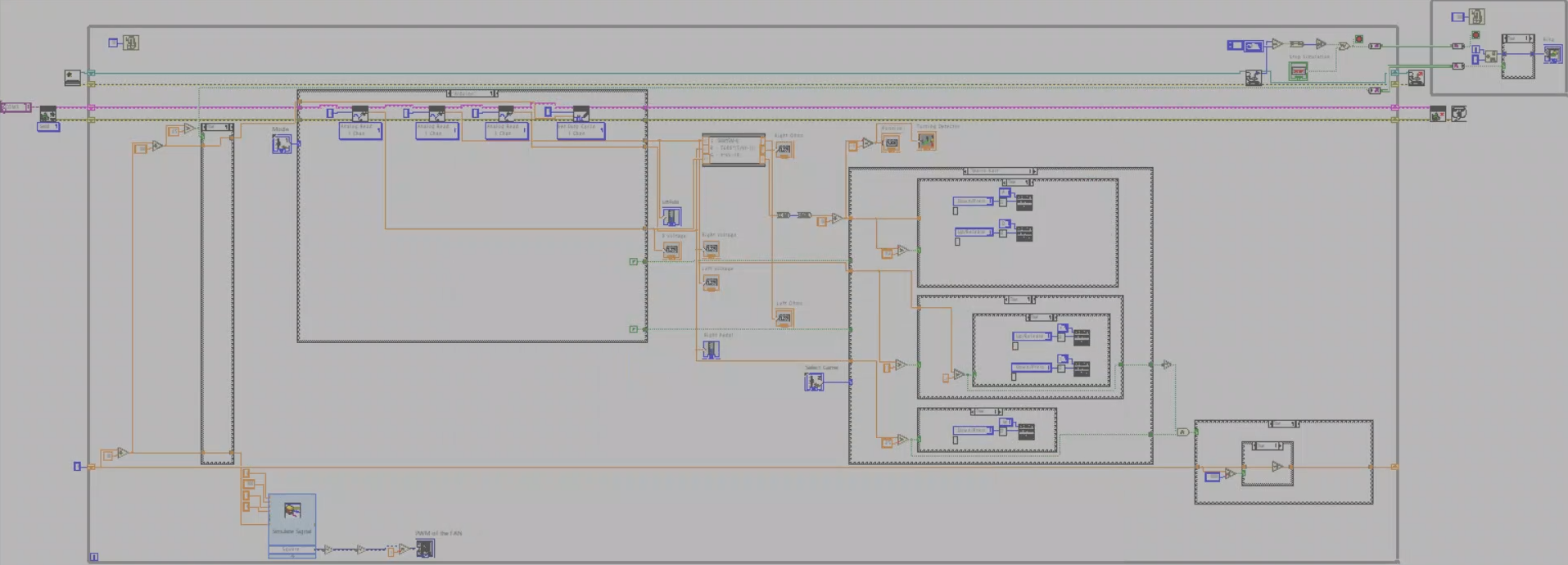 Figure 2: The LabVIEW Block Diagram handling logic flow and data conversion.
Logic Flow
- Data Acquisition: The system reads three analog channels (Steering, Gas, Brake).
- Conversion: The math derived above is applied in real-time to normalize values.
- Simulation Control:
- Steering: If normalized X > 0.2, send “Right” key; if < -0.2, send “Left” key.
- Pedals: Thresholds determine if the “Accelerate” or “Brake/Drift” keys are pressed.
- Fan Feedback: A counter increments as the gas is held. Once the virtual speed crosses a threshold, the Arduino writes a PWM (Pulse Width Modulation) signal to the fan, physically blowing air on the driver to simulate speed.
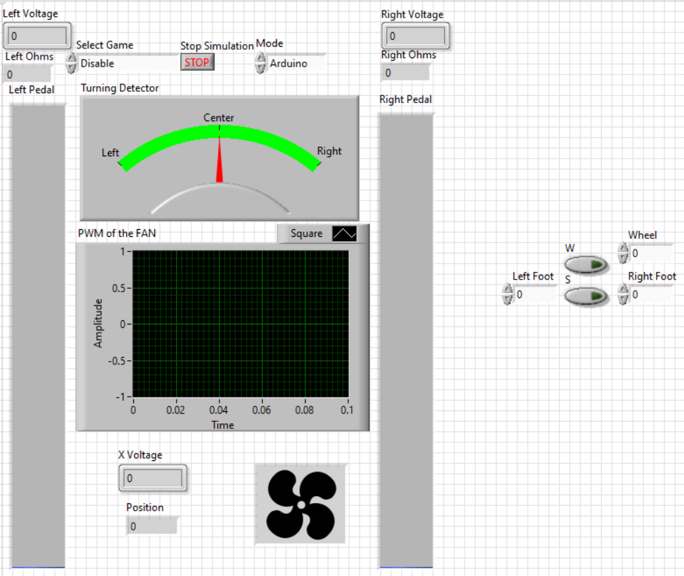 Figure 3: Front Panel of our LabVIEW code.
Results & Demo
The final system successfully interfaced with commercial racing games. The “Front Panel” in LabVIEW provided real-time visual feedback of the pedal pressure and steering angle, which matched the physical inputs perfectly.
Below is a demonstration of the system in action:
Novel Insights
Key Findings:
-
The Failsafe Bug: We discovered a specific bug in LabVIEW regarding Local Variables when implementing the failsafe stop button. The loop timing created race conditions. We solved this by using Channel Wires, which allow two independent loops (the logic loop running at 10ms and the visual loop at 100ms) to communicate asynchronously without data loss.
-
Immersion via PWM: The fan control required a “Kickstart” voltage. Simple linear mapping didn’t work because the fan wouldn’t spin at low duty cycles. We implemented a logic check where the PWM signal is only sent if the calculated value is above 0.5 (50% duty cycle), ensuring the fan actually runs rather than just humming.
-
Cost-Effective Haptics: While we couldn’t afford the force-feedback motors of the Logitech G923 (2.2Nm torque), the combination of the weighted Wii wheel and the air resistance from the fan provided a surprisingly convincing “pseudo-haptic” experience for a fraction of the price.
Conclusion
The DDPD project successfully demonstrated that complex sensor fusion and signal conditioning can be achieved with accessible hardware. By combining the mathematical rigor of transfer functions with the graphical programming of LabVIEW, we created a functional tool that meets the objective of providing a safe, simulated driving experience.
Future iterations would focus on replacing the cardboard chassis with a 3D-printed rig and implementing a more precise gyroscope for steering to eliminate the noise inherent in accelerometer-based tilt controls.